


Comments to date on DRAFT AES72-xxxx AES standard on interconnections - Application of RJ45-type connectors and quad twisted pair cable for audio interconnections
,
published 2019-02-15 for comment.
Please correct the nomenclature. It is 8P8C (8 position, 8 conductor) not 8C8P (see ISO 8877, TIA/EIA 568 et al). This is to differentiate e.g. 6P4C connectors which terminate a standard 4-conductor analog telephone line on a 6-position connector.
David Josephson, Josephson Engineering Inc.
David,
We will correct the error as an editorial change in the published version.
Best regards,
Richard Cabot
AES Standards Manager
Since I found the audio over QTP draft (great initiative) I like to comment the following.
1st. Please make STP or S/UTP cable mandatory. Not having a shield connection can make common mode voltages get out of range for non-transformer balanced inputs.
It also makes phantom power compatibility implicit.
2nd. Please just keep 1 standard pair pinout. Preferably the one with hot on 2 4 6 8 (logical and easy to remember). To have different ones marked with a small text like "type 3" next to the jack will just make the standard a non-standard.
Kind regards,
Rik van der Brugghen, Rikslab AB
Rik,
Thanks for your comments.
Section 4.3 does require shielded cable when phantom power is used. Fully balanced systems, particularly AES3 implementations where transformers are used, do not require any ground connection and so specifying shielded cable is unnecessary.
The scope states "This standard documents 8P8C (RJ45) pin-outs commonly used in analog and digital professional audio applications. .... Conformance with this standard will identify mutually compatible devices, enabling users to avoid problems when employing equipment from multiple manufacturers.
Standardizing one pinout was not the goal of the Working Group that developed the document. It is unlikely that agreement could be reached on one specific implementation. It is the groups expectation that one version will become dominant in the market and eventually most manufacturers will gravitate to that implementation. Until then, the labeling requirements will enable users to make appropriate equipment selection and will facilitate their pressuring manufacturers to shift to a common pinout.
Please reply by the end of the comment period if this reply is not acceptable to you. You may also ask us to consider your comments again for the next revision of the document. You may also appeal this decision to the Standards Secretariat.
Best regards,
Richard Cabot
AES Standards Manager
I see your point on shielded vs non-shielded cable, it depends on the application. But specifically for line level analog audio I would recommend shielded cable. It's the same sort of argument as for XLR pin 1. It -should- be connected from sender to receiver. It's to be viewed as an extension of the enclosure. If not connected, common mode voltage differences might clip the input stage. Maybe not if they are DC (filtered out by the input AC coupling) but if like 50/60 Hz it will affect input headroom.
About wiring, yes, maybe there will be a "gravitation" towards one implementation, so labeling of jacks will be needed so far. But can't the AES specify a preferred wiring so this gravitation is sort of encouraged? It's like with the MIDI mini-TRS thing, there were 2 wiring versions, but MIDI org decided to standardize one.
Also, any manufacturer (like me) who might want to -start- implementing QTP audio, likes to be future compatible. So I strongly suggest the AES to have a -preferred- solution recommended. In my view the hot 2 4 6 8 one, but you might find out what is already most wide spread and recommend that.
Best regards,
Rik van der Brugghen, Rikslab AB
Rik,
Thanks for your comments.
The mandate for this group was to develop a standardized way of representing the wiring of 8P8C connectors. Recommending one pinout is outside the Working Groups scope.
If we were to attempt to recommend or standardize one pinout we would be endorsing one manufacturers products at the expense of other manufacturers products. If the group was given the mandate to make such an endorsement, the standard would be held up for many months, probably years. The industry would not be well served by that delay.
Please reply by the end of the comment period if this reply is not acceptable to you. You may also ask us to consider your comments again for the next revision of the document. You may also appeal this decision to the Standards Secretariat.
Best regards,
Richard Cabot
AES Standards Manager
I propose a revised chart focusing the importance of TIA wiring schemes that all schemes are leveraging.
I propose a QTP code relative to the solid core wires.
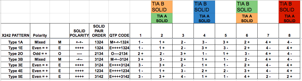 |
In talks with some colleagues, the cross over chart should be relative to the TIA wiring, not relative to the individual schemes.
Regards
Anthony P. Kuzub
Anthony,
The document is providing a way to label the connectors on equipment and doesn't deal with the cable or its conductor colors. Specifying in terms of the conductor color adds a level of indirection that may confuse users who are not dealing with cable conductors.
The proposed QTP code is more complex and may negatively affect manufacturers willingness to adopt it. Although the extra information may be helpful to some, most users are unlikely to care. The goal is to convey whether two devices will correctly interconnect. If a user does care about the specific channel order and polarity for a device they can obtain that information from the standard.
Implementation of a change of the magnitude you propose would send the document back to the committee for revision and add months to the schedule. I don't believe the industry would be well served by such a delay.
Please reply by the end of the comment period if this reply is not acceptable to you. You may also ask us to consider your comments again for the next revision of the document. You may also appeal this decision to the Standards Secretariat.
Best regards,
Richard Cabot
AES Standards Manager
You're right. It's the data set expanded.
I will say though, I brought this up at AES NYC so it's already been in committee meetings and it's in the original proposal. I originally included only the TIA-B but the proposed revision features both. All that I'm pointing out is a quick summary of the existing chart paying attention to the importance on the solid wires and how they are used.
May I then suggest one thing that help with the chart on 4.2
Color the positives with the resistor code.
1+ Brown
2+ Red
3+ Orange
4+ yellow
At AES NYC, I recall the conversation about putting the +ves in RED.
Combining the two charts (A3 and 4.2) was the original suggestion. It's so very hard to separate the importance of following the TIA-(A/B). I'm convinced. Reading this again I see comments about the pair colors being an annex... or application guide. Maybe I will expand on that.
Regards
Anthony P. Kuzub
Anthony,
The wire colors were in the original proposal and this was discussed extensively in several group meetings. The opinion of most group members was that the document should focus on connector pin numbers and relegate cable colors and other details to to an annex. The cable color information became Annex A and the implementation details from your original proposal became Annex B.
There was considerable aversion to anything that implied users should be cutting cables and wiring individual conductors to patch bays, other connectors, etc. Some of this cautionary material got added to Annex B in B6.
Adding resistor color code to the table is likely to spawn confusion as these colors have no relation to the cable, the connector, nor anything in the TIA or IEC standards.
Coloring the positive pins red was discussed in committee as a solution to the + and - symbols being difficult to see in the table. The solution I chose was to increase the font size of the + and -. They are currently larger (12 point) than the table text (10 point).
Please reply by the end of the comment period if this reply is not acceptable to you. You may also ask us to consider your comments again for the next revision of the document. You may also appeal this decision to the Standards Secretariat.
Best regards,
Richard Cabot
AES Standards Manager